- 您现在的位置:买卖IC网 > Sheet目录100 > NHD-12864WG-FTMI-VZ# (Newhaven Display Intl)LCD MOD GRAPH 128X64 WH TRANSM
[4]?
?
?
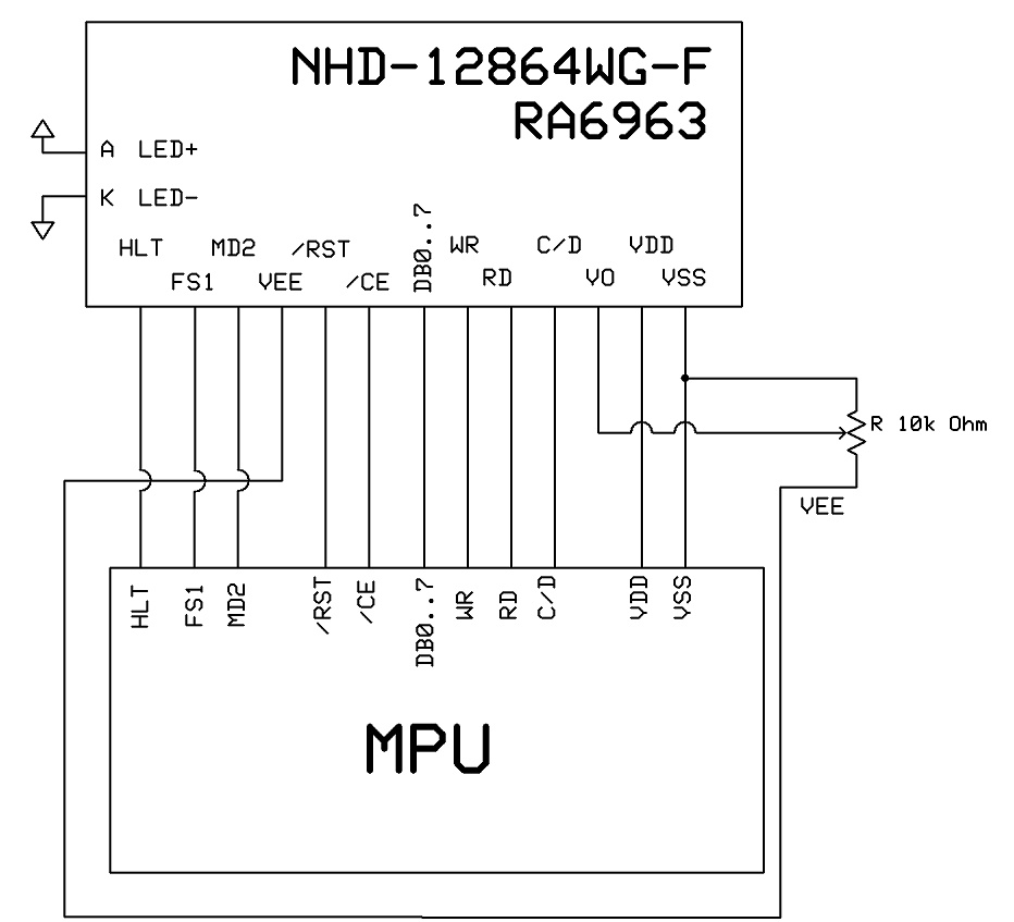
Pin?Description?and?Wiring?Diagram?
Pin?No.?
Symbol?
External?
Connection?
Function?Description
1?
VSS?
Power?Supply?
Ground
2?
VDD?
Power?Supply?
Power?supply?for?logic?(+5.0V)
3?
V0?
Adj.Power?Supply?
Power?Supply?for?contrast?(approx.?‐3.0V
)
4?
C/D?
MPU?
Register?select?signal.??C/D=0:?DATA??C/D=1:?COMMAND?
5?
/RD?
MPU?
Active?LOW?Read?signal
6?
/WR?
MPU?
Active
LOW?Write?signal
7‐14?
DB0‐DB7??
MPU?
Bi‐directional?8‐bit?data?bus?
15?
/CE?
MPU?
Active?LOW?Chip?enable
16?
/RST?
MPU?
Active?LOW?Reset?Signal
17?
Vee?
Power?Supply?
Negative?voltage?output??(‐5.0V)
18?
MD2?
MPU?
Column?select;??H:32?column;??L:?40?column
19?
FS1?
MPU?
Font?Select:??1:?6x8
fonts,???0:?8x8?fonts
20?
HLT?
MPU?
Clock?operating?stop?signal
A?
LED+??Power?Supply?
Power
Supply?for?LED?Backlight?(+3.5V)
K?
LED‐?
Power?Supply?
Ground?for?Backlight
Recommended?LCD?connector:?2.54mm?pitch?pins?
Backlight?connector:??‐????Mates?with:??‐?
?
?
?
?????????????????????????????

发布紧急采购,3分钟左右您将得到回复。
相关PDF资料
NHD-12864WG-FTTI-VZ#000
LCD MOD GRAPH 128X64 WH TRANSM
NHD-12864WX-T1TFH#
LCD MOD GRAPHIC 128X64 TRANSFL
NHD-14432WG-ATFH-V#
LCD MOD GRAPH 144X32 WH TRANSFL
NHD-160128WG-BTGH-VZ#-1
LCD MOD GRAPH 160X128 WH TRANSFL
NHD-160128WG-BTMI-VZ#-1
LCD MOD GRAPH 160X128 WH TRANSFL
NHD-16032AZ-FL-YBW
LCD MOD GRAPH 160X32 Y/G TRANSFL
NHD-16032AZ-NSW-BBW
LCD MOD GRAPH 160X32 WHI TRANSM
NHD-16032BZ-FL-YBW
LCD MOD GRAPH 160X32 Y/G TRANSFL
相关代理商/技术参数
NHD-12864WG-FTTI-V#Y
功能描述:LCD 图形显示模块和配件 128 x 64 FSTN(-) 87.0 x 70.0 RoHS:否 制造商:ELECTRONIC ASSEMBLY 产品: 分辨率:128 x 64 流体类型:FSTN Positive 接口: 背光: 背景色:White 工作温度范围:- 20 C to + 70 C 封装:Bulk
NHD-12864WG-FTTI-VZ#000
功能描述:LCD 图形显示模块和配件 FSTN (-) Transm 87.0 x 70.0 RoHS:否 制造商:ELECTRONIC ASSEMBLY 产品: 分辨率:128 x 64 流体类型:FSTN Positive 接口: 背光: 背景色:White 工作温度范围:- 20 C to + 70 C 封装:Bulk
NHD-12864WX-T1TFH
制造商:NEWHAVEN 制造商全称:NEWHAVEN 功能描述:Graphic Liquid Crystal Display Module
NHD-12864WX-T1TFH#
功能描述:LCD 图形显示模块和配件 FSTN (+) Transfl 38.0 x 24.2 RoHS:否 制造商:ELECTRONIC ASSEMBLY 产品: 分辨率:128 x 64 流体类型:FSTN Positive 接口: 背光: 背景色:White 工作温度范围:- 20 C to + 70 C 封装:Bulk
NHD-14432WG-ATFH-V#
功能描述:LCD MOD GRAPH 144X32 WH TRANSFL RoHS:是 类别:光电元件 >> 显示器模块 - LCD,OLED,图形 系列:NHD-14432WG-A 标准包装:1 系列:* 其它名称:Q7143510
NHD-14432WG-ATFH-V#T
功能描述:LCD 图形显示模块和配件 144 x 32 FSTN(+) 85.0 x 36.0 RoHS:否 制造商:ELECTRONIC ASSEMBLY 产品: 分辨率:128 x 64 流体类型:FSTN Positive 接口: 背光: 背景色:White 工作温度范围:- 20 C to + 70 C 封装:Bulk
NHD-14432WG-ATFH-VT
制造商:NEWHAVEN 制造商全称:NEWHAVEN 功能描述:Graphic Liquid Crystal Display Module
NHD-14432WG-BTFH-V#T
功能描述:LCD 图形显示模块和配件 FSTN (+) Transfl 80.0 x 36.0 RoHS:否 制造商:ELECTRONIC ASSEMBLY 产品: 分辨率:128 x 64 流体类型:FSTN Positive 接口: 背光: 背景色:White 工作温度范围:- 20 C to + 70 C 封装:Bulk
